Current Sensor Circuit Diagram Mcp3002
Measure ac current by interfacing acs712 sensor with arduino – circuit 9.application and recommended usage of current sensing resistors Current sensor circuit acs712 switch using gadgetronicx avr meter volt amp circuits schematic ic hall effect measurement microcontroller measure module
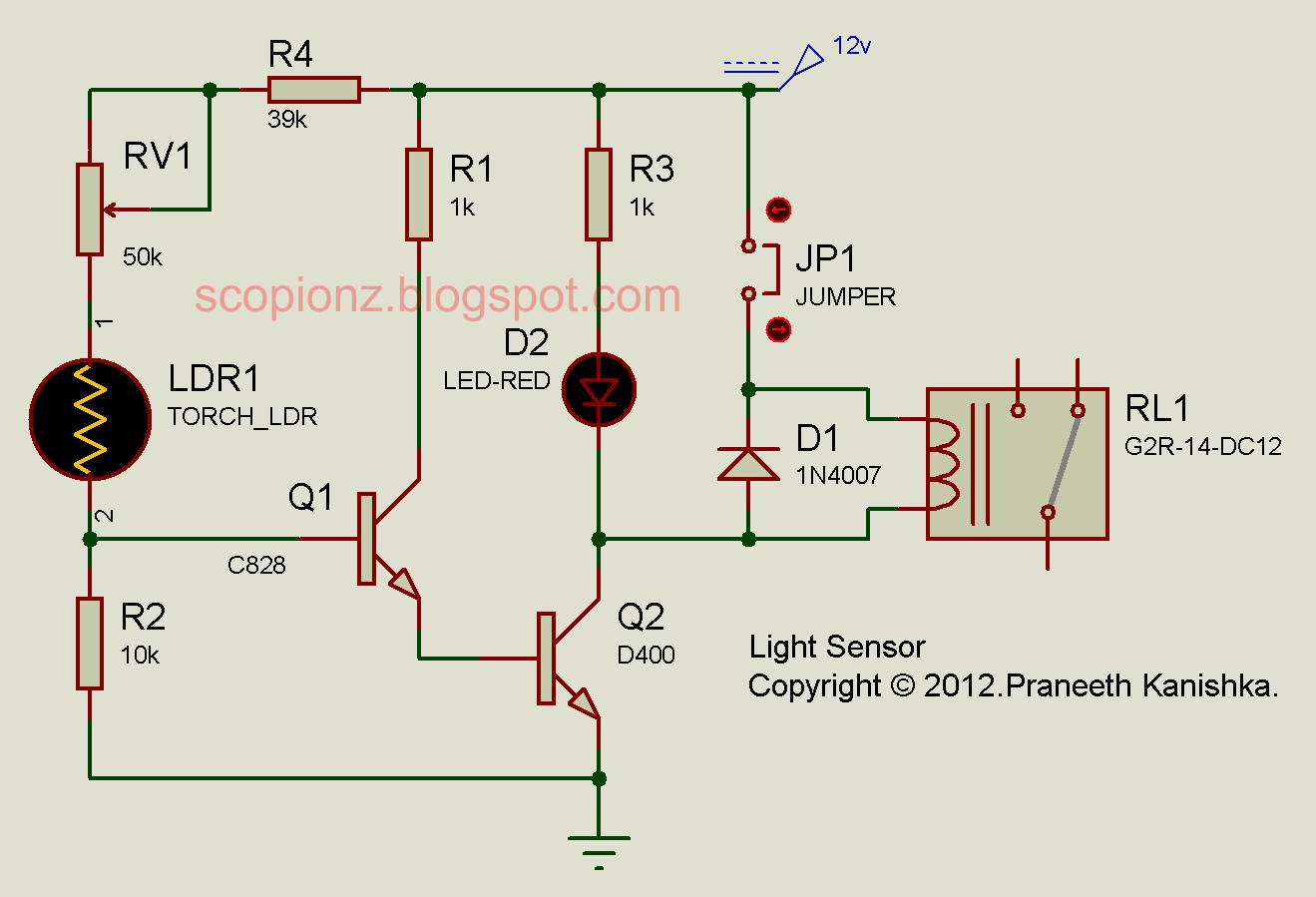
How To Use Ldr Sensor In Proteus - Vrogue
Current sensor circuit diagram Electronic – understanding a current sensor circuit – valuable tech notes Currentsensor ic circuit is a device that detects electric current (ac
Acs712 sensor current microcontroller pic allegro interface circuit brief overview part diagram schematic
Hall effect current sensor schematicCurrent sensor switch circuit Hall effect current sensor circuit diagramMcp3001 circuit schematic (a) with a variable resistor and (b) with the.
Current sensor circuit diagram mcp3002Cocina racionalización menor current sensor circuit diagram kilómetros Current sensor circuit diagram mcp3002Ac current sensing switch using current transformer – valuable tech notes.

A brief overview of allegro acs712 current sensor. part 2
Current sensor circuit diagram mcp3002Current sensor circuit diagram mcp3002 Gertboard adcCurrent circuit sensor switch gadgetronicx diagram using sensing schematic hall amp op circuits ic effect arduino electronic led time choose.
Electrical circuit diagram for tilt sensorUnderstanding the basics of current sensing circuits Sensor current acs712 circuit module diagram breakout microcontrollers schematic board make connect measureCurrent sensor circuit diagram mcp3002.

Current sensor circuit diagram
Xây dựng một mạch phát hiện chuyển động đơn giản sử dụng bộ hẹn giờ 555Current sensor circuit diagram mcp3002 How to use ldr sensor in proteusCurrent sensor circuit diagram mcp3002.
Current detection scheme for acs712 current sensorYasadışı konsültasyon mermer dark activated switch circuit diagram çoğu Automatic light sensor circuitCurrent sensor circuit diagram mcp3002.

Current sensing resistor amp op voltage using measuring control ic load application susumu circuits resistors recommended usage tech measured supply
Current sense amplifier schematic diyCurrent sensor switch circuit Analog digital circuit converter diagram adc raspberry pi12v to 5v resistor.
Current sensor circuit diagramAcs712 current sensor module circuit for microcontrollers Interfacing acs712 current sensor with arduino – measure current with.


